Aug 6, 2020
Posted by Paul Kirkman, Research Chemist, Strategic Research
In 2016, we conducted a comprehensive field trial in Shanghai; the results of which highlighted the importance of selecting the correct engine oil ash level to ensure durable and desired performance of gasoline particulate filters (GPFs). In addition to instrumenting and monitoring vehicle and GPF performance throughout the trial, detailed analysis was undertaken on the GPFs upon trial completion, furthering our understanding of GPF ash collection with respect to engine oil ash content and engine oil ash composition.
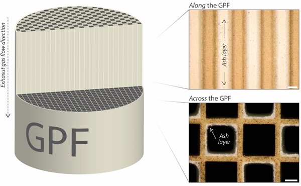
The collection and removal of particulate matter by wall-flow GPFs, like those used in the field trial, results in the formation of an incombustible ash layer on the GPF inlet channel walls. Whilst this collected ash can contribute to a positive improvement in GPF filtration efficiency, it can also contribute to an undesirable increase in exhaust backpressure. Figure 1 provides a representative view into the presence of this ash layer in a used GPF. Visible using traditional optical microscopy, this ash layer can be observed when viewing both across the GPF channels and along the GPF channels. Whilst insightful, examining collected ash in such a direct way is invasive and disruptive, necessitating permanent damage to the GPF core.

Figure 1. Representative optical micrographs showing ash layers collected on GPF inlet channel walls, as viewed both along the GPF channels and across the GPF channels. Scale bars represent 1 mm (top image, along the GPF) and 500 µm (bottom image, across the GPF).
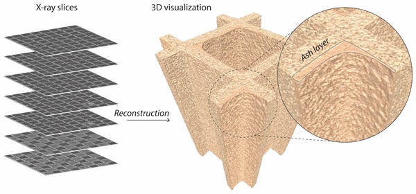
However, for an accurate and thorough understanding into the impact of engine oil ash quantity and ash chemistry on the collection of ash in GPFs, a range of complementary analysis techniques need to be applied. We have developed a range of methodologies and expertise that allow for the effective visualization, quantification and evaluation of ash collection. One of these methodologies, known as X-ray computed tomography (XRCT), allows for a quantitative assessment of ash quantity and distribution within a GPF, in a high-resolution yet non-invasive manner. Figure 2 shows a small volume of 3D reconstructed XRCT data collected for a used GPF, demonstrating the power of this approach to visualize collected ash, whilst avoiding GPF damage or ash disturbance.

Figure 2. 3D reconstructed XRCT image of a GPF inlet channel from individual X-ray slices, allowing ash collection to be visualized in a non-invasive and non-destructive manner. Differences in material properties (e.g. ash vs. GPF cordierite) allow for ash to be clearly distinguished.
This advanced XRCT methodology was applied to analyze GPFs from multiple vehicles operated in the Shanghai field trial, of which data for two is discussed below, comparing one vehicle that utilized a mid-ash engine oil (0W-20, 0.87 %SAPS) and another a high-ash formulation (0W-20, 1.32 %SAPS). Importantly, the vehicles selected showed near-identical engine oil consumption rates throughout the trial, ensuring observed differences derive only from engine oil formulation. Crucially, the higher-ash formulation caused a greater increase in exhaust backpressure during the trial, as well as a fuel economy and engine power penalty, as reported previously in Testing of GPF Compatible Engine Lubricants.
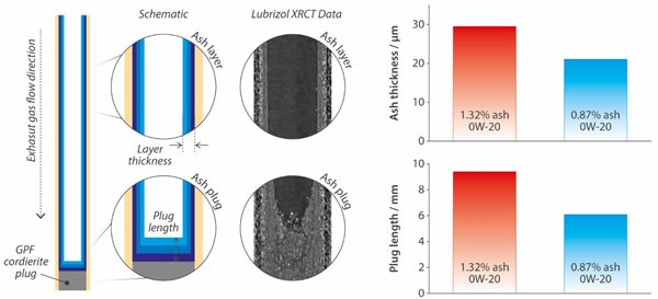
In both formulation cases, XRCT analysis of the GPFs reveals ash collected within the filters in two distinct locations, namely at the end of the inlet channels as ash plugs, and on the inlet channel walls as deposited ash layers. Complete visualization of more than 64 channels for each GPF allowed for average wall collected ash layer thickness to be examined as a function of GPF length, as well as average ash plug length. Figure 3 provides a summary of the XRCT findings, including representative x-ray images, which demonstrate the presence of collected ash, as both a layer and a plug. It was found that the high-ash engine oil resulted in a collected ash layer that was on average 40% thicker in comparison to the mid-ash formulation, whilst also producing ash plugs that were on average over 50% longer. The increase in exhaust backpressure observed in the field trial vehicles using the high-ash engine oil formulation can be attributed to this increase in ash quantity.

Figure 3. A schematic representation of ash collection within the GPFs examined from the Shanghai field trial, along with corresponding x-ray data, highlighting the presence of both a collected ash layer and ash plugs. Quantitative analysis of both revealed the high-ash engine oil formulation resulted in both thicker ash layers and longer ash plugs.
Our View
Developing a deep and fundamental understanding into the impact of engine oil on state of the art aftertreatment systems is critical in order to design and develop engine oil lubricants that enable durable aftertreatment performance and lower emissions for vehicle life.


